Page 13 - Oil & Gas Final
P. 13

13.594
                                                  12.083                                        2
                                                  10.573                                        1.78
                                                  9.062                                         1.58
                                                  7.552                                         1.33
                                                  6.042                                         1.11
                                                  4.531                                         0.89
                                                  3.021                                         0.67
                                                  1.510                                         0.44
                                                  0                                             0.22
                                                  velocity (m/s)                                0
                                                                                                pressure (bar)


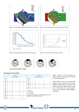
                Fig. 6 – CFD showing the velocity reduction inside the trim (VP2 G).  Fig. 7 – CFD showing the pressure reduction inside the trim VP2 G.


                      5.9E+005                                     800
                     Static pressure <Pa> (MIN: 497518, MAX 5887  5.6E+005  700                Cv ISA 75.02
                      5.8E+005
                      5.7E+005
                      5.5E+005
                                                                   600
                      5.4E+005
                                                                   500
                      5.3E+005
                                                                   400
                      5.2E+005
                                                                                               Cv ISA 39.2
                      5.1E+005
                                                                   200
                      5.E+005
                      4.9E+005                                     300
                                                                   100
                         0                    50                    100                 150                 200                 250                   300                350
                           Parametric Distance <millimeter> (min: 0, max: 310,882)  0
                                                                     0    20    40    60    80
                        Curve legend 15m3_hx2
                Fig. 8 – Step-wise pressure drop curve inside the body cavity.  Fig. 9 – CV curve of a DN 100 valves with 90° V-ball.


                Fig.10 – 90°, 60° and 30°-60° V-Shape.


       Valve design & trims available

                     Trunnion                             Floating              Patterns  customized  on  process  parameters  are
                   Rating 150/300/600                Rating 150/300 (PN/40)     available, as well as on pressure classes not mentioned
        SIZE                               SIZE                                 on the present standard table.
         3”    •         •         •       1/2”   •         •
         4”    •         •         •       3/4”   •         •                   Valpres control ball valves can be supplied with
         6”    •         •         •       1”     •         •
         8”    •                   •       1”1/2   •        •                   pneumatic, electric or hydraulic actuators and electro-
        10”    •                   •       2”     •         •                   pneumatic  or  SMART  positioner,  sourced  from  main
        12”    •                   •       3”     •         •           •       approved suppliers in the Oil&Gas market. For valves
        14”    •                   •       4”     •         •           •
        16”    •                   •       6”     •         •           •       up  to  8”  600#  Valbia’s  rack  and  pinion  pneumatic
        18”    •                   •                                            actuators may be used (see also Valbia catalogue or
        20”    •                   •      • VP0 TRIM                            www.valbia.it).
        24”    •                   •      • VP-VBALL TRIM
        30”    •                   •      • VP1-VP2 TRIM
        36”    •                   •     For 900#, 1500#, 2500# valves contact BONOMI UK sales office.
        40”    •                   •     Customized trims available upon request.
        42”    •                   •
        48”    •                   •


                                                                                                                 13
   8   9   10   11   12   13   14   15   16